
RFID Race Timing Systems. Converted from the Word original (V1.2, 27 November 2025) so it can be kept current in one place. Section numbering follows the original.
1.0 Introduction
EchoActive Plus is a dual transponder system. Both UHF Gen 2 tags and proprietary EchoActive tags can be read with the same decoder box. The Plus variant includes the latest Gen 2 UHF reader for reading of low-cost disposable and reusable 900 MHz passive UHF tags. EchoActive (active tags) is a new timing technology that uses dual frequencies to trigger and then download data from active transponders worn by the participants. Because the transponders are battery powered the read performance is 100%. The transponder is triggered by a low frequency loop placed out on the road or path. A precise time is recorded when the transponder is exactly between the two ‘tram-lines’ of the loop and this time plus other data is sent back to the Base over a high frequency link. Table 1. Differences between active and passive reading systems on EchoActive+
| Property | EchoActive | UHF Gen 2 |
|---|---|---|
| Read performance | 100% | 99.5% + |
| High Speed performance | Up to 110 km/h | Up to 50 km/h |
| Ground Antennas | Single wire loop up to 12 m wide | Individual antennas connected via coax cable to decoder port |
| Transponder Cost | High | Low |
| Recommended sports | Cycling, triathlon, motocross | Running |
2.0 Transponders
2.1 UHF Gen 2
Transponders are called various names such as tags or RFID chips. The UHF tag is generally low in cost and contains no battery so it derives its energy from the reader signal. They are often supplied on foam spacers to avoid the negative read effects of an athlete's skin (water). They are usually placed on the back of an athlete's race number bib. Our systems read the lower 32 bits of the EPC code and displays this as a decimal number. There are also reusable UHF tags which have an infinite life and are generally worn on the athlete's ankle via a strap.
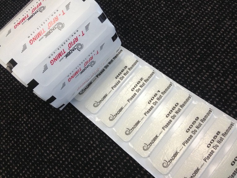
Fig 1. Disposable encoded UHF tags on roll.
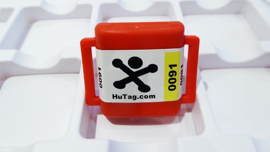
Fig 2. Reusable UHF Hutag worn with ankle strap (not shown).
2.2 EchoActive
A transponder is carried by the participant either attached by an ankle strap or cable tied to a bicycle/vehicle. The EchoActive transponder spends most of its time in deep sleep mode only being ‘woken’ by a signal from the wire loop on the ground. The transponder will reply with its unique 6 character alphanumeric code plus other diagnostic data at the completion of the trigger phase. The reply signal is picked up by the Base and acknowledged. After this the transponder re-enters a sleep state waiting for the next trigger signal. The transponder is fully sealed inside a polycarbonate housing for complete waterproofness and shock resistance. A lithium CR2032 battery is permanently installed with a finite lifespan depending on the number of trigger events and time spent in different modes of operation. It is very important to understand the different modes of operation of the transponder to maximise the lifespan of the battery.
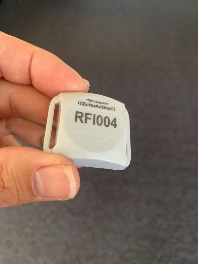
Fig 3. EchoActive transponder
3.0 EchoBase+ Decoder
The Base houses all the systems that trigger and read transponders as well as set and keep accurate time. Data is saved in an internal flash file system for later ‘rewind’ over Ethernet. There is also an option to fit a 4G modem if data from the Base is to be sent remotely. The SIM card slot is inside the case on the main PCB.
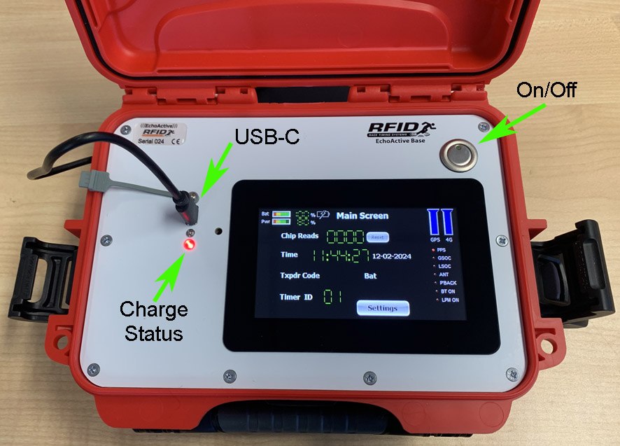
Fig 4. Top panel of the EchoBase+
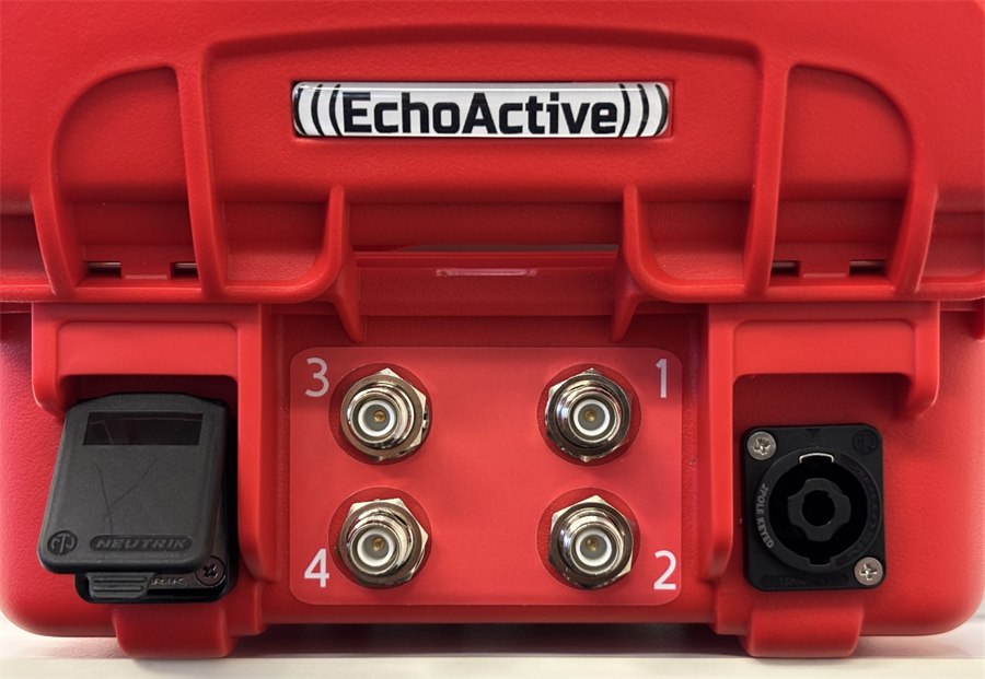
Fig 5. Rear of EchoActive+ Base showing external connectors – Ethernet jack (right), 4 UHF antenna ports and active loop port (left). Coax connectors shown are RP-TNC and can be optionally fitted with BNC.
3.1 On/Off Button
The silver button immediately turns on the Base. After a few seconds the Base will go to the Main Screen and be ready to read transponders. The user should give the Base at least a few minutes for the GPS satellites to receive a time fix. Holding the button down for 3 seconds will turn off the Base. A flashing green light indicates that the UHF reader is switched on and in read mode.
3.2 LCD Screen
A sunlight readable touchscreen is used to access many of the settings of the Base. It is advisable to use the screen sleep mode to greatly extend the battery life of the Base.
3.3 USB
There is a USB-C socket for recharging the internal battery with the supplied wall plug and cable. A red LED indicates charging while a green LED indicates charging is complete. The LED is unlit if no charger is plugged in. The average power use (in amps) of the Base is less than the maximum charge current of the charger. The USB-C PD (power delivery) is set for multiple configurations depending on the wall charger. It is recommended that a certified USB-C fast charger is used that can deliver at least 12 V at 1.67 A. Charging takes up to 8 hours with an 18 W USB charger. A USB powerbank can also be used as a hot-swappable power source.
3.4 Ethernet Jack
On the back of the box is the Ethernet jack used for communication with the system using a standard 10/100Base-T Ethernet cable. The socket accepts a positive lock Neutrik Ethernet shroud (NE8MX). The ethernet can be configured to accept static and dynamic IP addresses. If you do not understand TCP/IP and network IP addresses there are plenty of tutorials to be found on the internet. It is strongly recommended that the user understands the differences and setting of IP addresses of devices on the network.
3.5 GPS
Setting the time of the Base is automatic and done via GPS. It will take between 50 seconds and several minutes for the GPS to get a valid satellite fix enabling accurate time calculation. The accuracy is within several microseconds of atomic UTC time. The GPS satellites will still be available with the lid closed. GPS time ensures all Bases are synchronised with the exact same time. The 1 second pulse on the PPS signal (Main Screen) signifies a valid time fix. If you want to manually set the clock this can also be done using RFIDServer. If manually setting the clock time remember to turn off the GPS time sync function (Time Settings menu).
3.6 4G modem and SIM Card Slot
The inbuilt 4G modem is an optional extra. It allows the telemetry of timing data to a relay server on the internet, which is Podium, our cloud based scoring software. Timing data is sent to the server, where it is scored and made available to the timing software. The server acts as the intermediary or relay between the Base and the timing software. Search our website for further information on how to set this up in Podium. The SIM card slot is accessed by carefully lifting the top panel once the 8 screws are removed. The reader wire harness will only allow the panel to be lifted slightly so it is important to note the location of the SIM card slot in the photos below. The SIM card slot will be on the right hand side of the main PCB in the location identified in the pictures (Fig 6). SIM cards should remain permanently in the slot due to the time-consuming process of removing and accessing the main circuit board. Most data SIMs can be purchased cheaply and recharged via the vendor's web app. To insert the full-size SIM card, follow the sequence of photos below. The SIM card will click when inserted into the locked position. To remove the SIM card push in the card's edge and the card will unlatch and spring out.
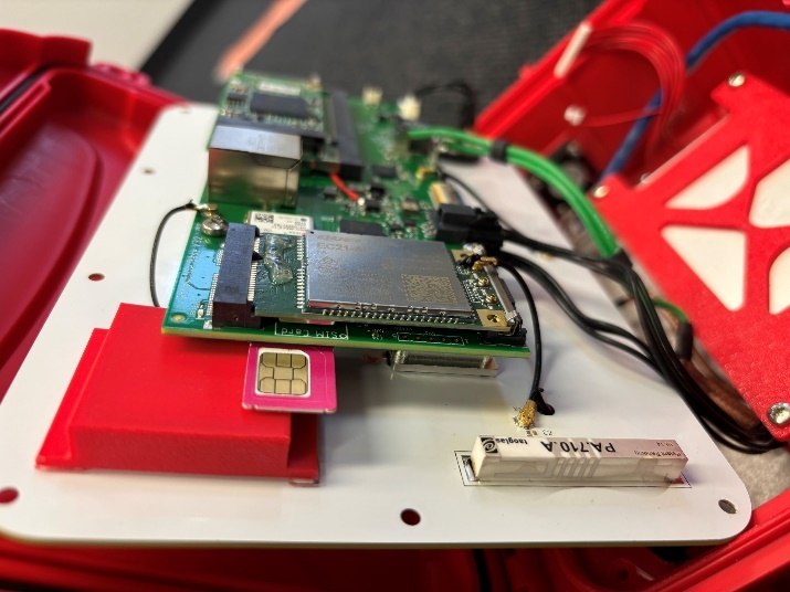
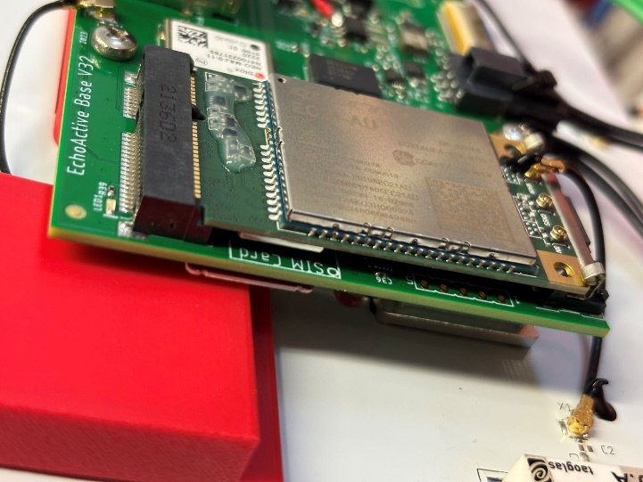
Fig 6. Insertion of the SIM card on the main PCB board. Also shown is the location of the 4G modem and modem antenna (PA710A).
3.7 Active Antenna Loop
On the rear of the Base enclosure is a 2 pole Neutrik plug (NL2MP) for the EchoActive wire loop. Insert then twist for correct connection. To unlock, pull the metal locking tab back and twist the plug anti-clockwise. This function is not used when the base is configured for reading UHF tags.
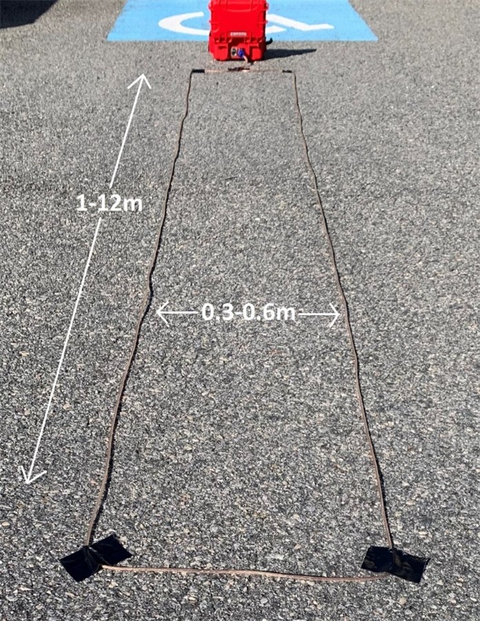
Fig 7. Example of initial placement of wire loop (example is 0.3 x 4m) The specification of the wire loop is not stringent and most multistrand copper wire will suffice. The loop can be varied in size from 1 to 12 m long with a gap in the ‘tram-line’ of between 30 and 60 cm. Transponders passing across the loop at faster than 70 km/h should use the wider 60 cm loop. The loop is connected to a 2 pole Neutrik plug which you insert and twist for a positive lock to the socket on the back of the Base. The rectangle loop shape is maintained using gaffer tape, bitumen nails or placed under grass using a small cable trench digger. The loop can also be placed within a rubber mat for easy deployment without the need to tape it down. This latter method is recommended for narrower timing points on grass and loose ground. Cycling events on road should use the tape down method. If the tape will not stick in wet conditions then the loop rectangle can be held down by bitumen nails. It is very important to make sure this loop stays on the ground during the passing of bicycles and vehicles or injury to participants may occur.
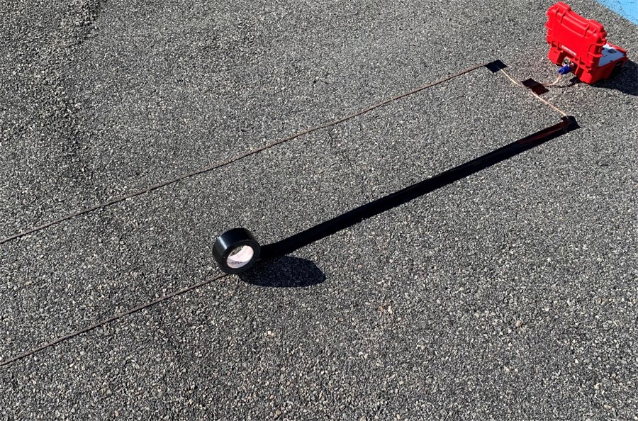
Fig 8. Taping the loop wires down with gaffer tape. A white finish line can be placed in the middle of the tram lines.
3.8 UHF Antenna Ports
There are 4 coaxial connectors on the rear of the Base that connect to UHF antennas. These can be either the screw on type (RP-TNC) or bayonet type (BNC) and are an option that the user can order. The antennas come in many forms (mat or side antenna) and frequencies (EU or FCC). The best type of antenna depends on the type of event being timed. Contact RFID Race Timing Systems for guidance on what type to use and how many units are required.
4.0 Settings
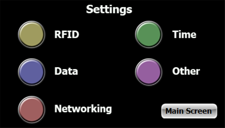
This screen is the main entry point for changing many of the Echo settings. Press the button to go to the various pages or press Main Screen to return to the main reading screen.
4.1 Main Screen - UHF
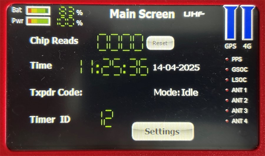
Bat (Base Battery Percentage)
This denotes the amount of battery storage of the unit. The Base uses a sophisticated current counter IC that keeps track of the battery capacity and displays this value in percent. The system should be immediately charged below 10% and will shut-down below a pre-determined supply voltage which usually equates to below 1%.
Pwr
Not used.
Chip Reads
The number of transponders (chips) read since the unit was turned on. It can be reset to zero with the Reset button.
Time
The local time of the internal clock. This time uses exact GMT (Greenwich Mean Time) with the timezone setting to determine time and date. When the unit powers up the time is immediately retrieved from the accurate internal time chip. When a PPS signal is fixed from the GPS the time is recalibrated to precise GPS time. This is currently only done once on a powered-up Base. The time drift of the internal time chip is less than 0.5 seconds over 24 hrs.
Txpdr Code
The transponder code can be a 32 bit number (Gen 2 UHF) or a six character code (EchoActive) of the last transponder to be read since power up of the Base. The transponder codes can be requested by the user when transponders are programmed during manufacture and stay with the life of the transponder. The transponder's code is therefore read-only. If the trigger is pressed (and turned on) then ‘TRIGGR’ will display.
Mode – UHF Gen 2 Only
This will display whether the UHF reader is actively reading or in idle mode. When in idle the reader will not read UHF transponders and power use will be less than 50%.
Timer ID
Not important for UHF operation.
GPS and 4G
Both these ‘tank symbols’ in the top right hand corner of the screen denote GPS and 4G signal strengths. The 4G signal will only be shown if a modem is installed and Remote is turned on (see Networking).
LED Status Bar
PPS – This LED will pulse on and off each second if a valid time is available on the GPS. If the synchronisation of accurate time on each Base is required then it is important that this signal pulse can be seen. GSOC – Active connection to the cloud relay server. This is a special cloud service developed by RFID Race Timing Systems which accepts transmissions of raw timing data over the internet and stores this data on a server. LSOC – Local active ethernet socket connection. This will be lit if connected to an external computer and socket is active for 2 way data transmission using RFIDServer or 3rd party scoring software. PBACK – Playback mode of transponders. If this is set in the RFID menu, the transponders will reply with their most recently recorded times (see 2.0.4 Playback Mode). Normally this should be turned off as it will greatly reduce the number of transponders read per second. BT ON – Bluetooth mode of transponders. This is also set in the RFID menu and when turned on will set the transponder to Bluetooth mode (see 2.0.3). Normally this should be turned off if you are not using another device to pick up the transponder in BT mode. These devices are currently not available at the time of writing this manual. LPM ON – Low Power mode is on. Will put transponders in lowest power usage in sleep mode (see 2.0.2). This mode can be turned on if the timing point is the last one to be used in the event (i.e. finish line). Make sure this LED is lit before putting transponders to sleep prior to storage. It is set in the RFID menu. ANT 1..4 – When the reader is started (read mode) it will check for antenna connection on each of the 4 external coaxial connector ports. If a correctly functioning antenna is detected then it will be used for reading transponders. A minimum of 1 antenna must be connected for the reader to start. If 2-4 ports are connected then the reader will rapidly cycle between each port when searching and reading tags. This allows a wider read field on the timing point. Some antennas will not work if they are damaged or have a poor return loss.
4.2 Main Screen - EchoActive
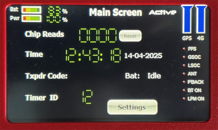
Bat (Base Battery Percentage)
This denotes the amount of battery storage of the unit. The Base uses a sophisticated current counter IC that keeps track of the battery capacity and displays this value in percent. The system should be immediately charged below 10% and will shut-down below a pre-determined supply voltage which usually equates to below 1%.
Pwr
This denotes the amount of power delivered to the loop. A lower value reduces the on time of the push pull transmitter reducing the peak voltage of the AC output signal. The user will notice a reduction in the height and distance from the loop that a transponder is triggered when the power is reduced. In most cases power can remain at 100% but the user can experiment with lower values to improve the precision of the triggered time on a transponder. Also if the transponder is low to the ground then the power can be reduced. There is negligible reduction in current use of the Base with reduced loop power.
Time
The local time of the internal clock. This time uses exact GMT (Greenwich Mean Time) with the timezone setting to determine time and date. When the unit powers up the time is immediately retrieved from the accurate internal time chip. When a PPS signal is fixed from the GPS the time is recalibrated to precise GPS time. This is currently only done once on a powered-up Base. The time drift of the internal time chip is less than 0.5 seconds over 24 hrs.
Bat (Transponder battery voltage)
When a transponder is read by the Base, the battery voltage of the coin cell within the transponder is also measured. This measurement is taken during a high current draw on the battery and does not correlate to the voltage of the battery when the transponder is in sleep mode. The transponder is close to the end of its life when voltage is below 2.0V and may not trigger at a voltage of 1.8V and below. Voltage of new transponders will be above 3.0V but will spend most of their lives around 2.6V as the voltage to charge curve is not linear.
Timer ID
Each Base must have a unique Timer ID set in the RFID screen. The Timer ID is output on the loop so that only transponders triggered by that loop will be read. Having two Bases with the same TimerID will result in transponders being triggered on one loop and possibly being read on the other Base. It is very important that Timer ID is set differently on multiple Base units.
GPS and 4G
Both these ‘tank symbols’ in the top right hand corner of the screen denote GPS and 4G signal strengths. The 4G signal will only be shown if a modem is installed and Remote is turned on (see Networking).
LED Status Bar
PPS – This LED will pulse on and off each second if a valid time is available on the GPS. If the synchronisation of accurate time on each Base is required then it is important that this signal pulse can be seen. GSOC – Active connection to the cloud relay server. The server service has been developed by RFID Race Timing Systems which accepts transmissions of raw timing data over the internet and stores this data on a server. Podium in the cloud scores with this remote data. LSOC – Local active ethernet socket connection. This will be lit if connected to an external computer and socket is active for 2 way data transmission using RFIDServer or 3rd party scoring software. ANT – Reserved. Not currently used. PBACK – Playback mode of transponders. If this is set in the RFID menu, the transponders will reply with their most recently recorded times (see 2.0.4 Playback Mode). Normally this should be turned off as it will greatly reduce the number of transponders read per second. BT ON – Bluetooth mode of transponders. This is also set in the RFID menu and when turned on will set the transponder to Bluetooth mode (see 2.0.3). Normally this should be turned off if you are not using another device to pick up the transponder in BT mode. These devices are currently not available at the time of writing this manual. LPM ON – Low Power mode is on. Will put transponders in lowest power usage in sleep mode. This mode can be turned on if the timing point is the last one to be used in the event (i.e. finish line). Make sure this LED is lit before putting transponders to sleep prior to storage. This is set in the RFID menu.
5.0 RFID Menu
This menu is the first of the settings menus that can be selected from pressing the Settings button on the Main Screen. It controls the wire loop signals that turn on/off certain transponder functions.
5.1 UHF
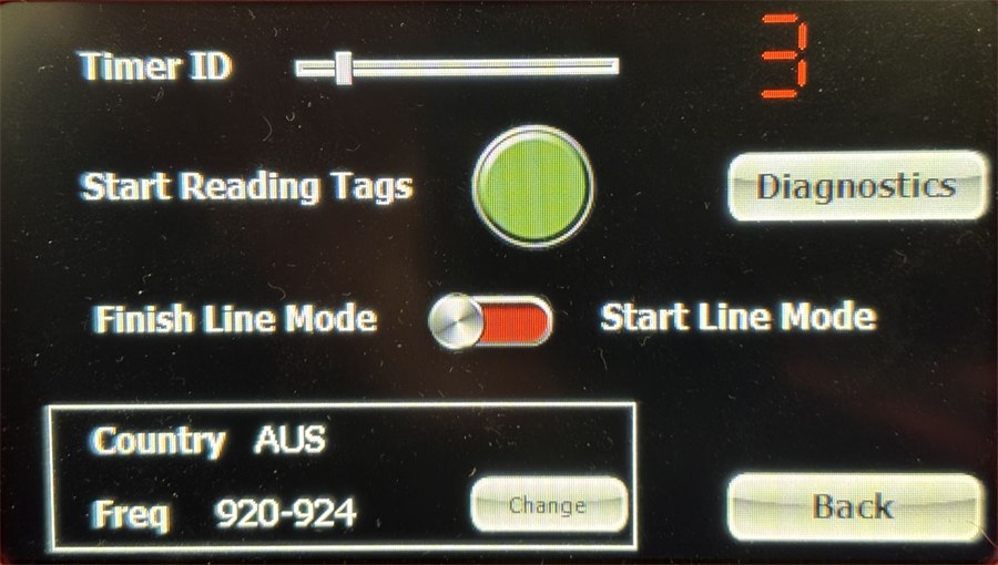
This menu controls some of the functions of the UHF reader prior to reading tags. The large green button puts the reader into initialisation and reading mode. If antennas are connected and their return loss checks pass, there will be a double beep and the screen will change to the main screen. See the purpose of TimerID in the EchoActive section. It is sent as a raw data field in an active connection over ethernet or remotely.
Finish/Start Line Modes
Finish line mode puts the reader in a high tag read rate that is best for timing a finish line. This should be the default setting for most races. Start line mode uses special Gen 2 reader settings that work best when there are a lot of transponders in the area. This setting should be used at a start line where many athletes are amassed on a wide start line.
Frequency
The country frequency is set at our factory and is not to be changed. It is important that the correct frequency and power levels are selected for the country where the system will be used. Non-conformance may result in severe penalties from the local regulatory authority. Antennas are also generally tuned for the particular frequency so ETSI frequency on FCC antennas will result in poor performance.
Antenna Diagnostics
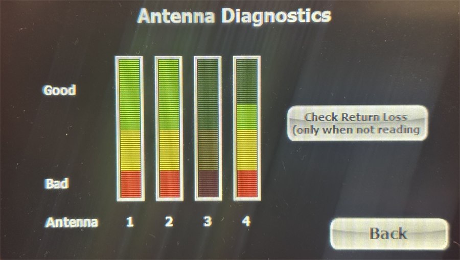
Return Loss
Pressing the Diagnostics button allows the user to check several antenna performance parameters. The first is Return Loss of each antenna port. Return Loss is a value given to the radiating power of an antenna with greater loss equating to better antenna performance. The Good and Bad values correspond to good and bad return loss for the type of antenna used in race timing. It takes about half a second per antenna to update the return loss signal bars. As the button denotes, this will only be possible when the reader is not in read mode. If the return loss is bad we suggest checking all antenna connections. If the problem persists then swap the antenna for another one making note that the antenna and cable may need to be repaired or replaced.
Tag RSSI
Once the reader is in read mode you can go back to the diagnostics screen and each antenna port will show the RSSI (received signal strength indicator) of tags when they are read. This is a dynamic reading on each port so moving the tag across each antenna should display the corresponding read strength of the tags. Bad or no read performance may indicate a damaged or unconnected antenna. Note that RSSI will be reduced as the tag is placed further away from the antenna.
5.2 EchoActive
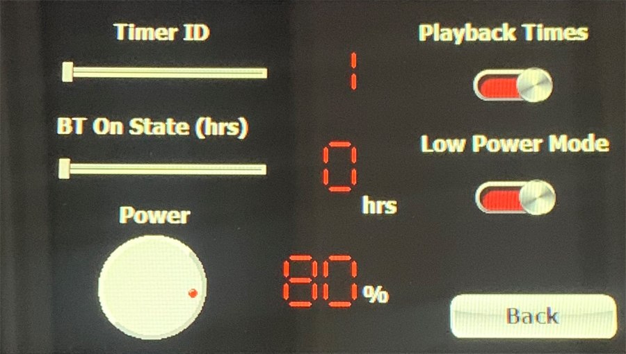
TimerID
The slider control changes the TimerID from 1 to 16 allowing for up to 16 different Bases to be used in the same area (400 m radius). This function ensures that a transponder triggered by a loop is read by the same Base only. If only one Base is being used then TimerID is of no importance. It is very important to not have two or more Bases operating in the same area with the same TimerID. This may cause a chip triggered on one Base to be read on a separate Base.
BT On State (hrs)
This is a special setting that will immediately instruct the transponder to send periodic Bluetooth advertisements. The transmissions can be received by any Bluetooth device and a moderately precise timestamp can be recorded by this device based on strongest RSSI of transmission. The EchoActive Nano is the device that can receive these transmissions. This device has an inbuilt 4G modem and can relay the time and transponder code to a remote server. The data is also saved internally on the device for later download via USB. An Android app is also possible to do the same function as the EchoActive Nano. If the BT mode is not needed then it should be turned off. The duration of BT mode can be set by the Base between 1 and 24 hours. BT mode can always be turned off prematurely by a Base set to 0 for BT mode. It is important to not choose too long a BT mode time if it is not needed to save battery usage. This slider ranges in times from 1 to 24 hrs and sets the transponder into Bluetooth mode (see 2.0.3). Once the transponder has crossed the loop with this set to greater than 0, it will emit a Bluetooth advertisement every second. This data can be picked up by any Bluetooth central device. In future the EchoActive Nano will perform this function. There is also a free Android app that demonstrates this feature. In normal use this is set to 0 (off).
Power
Sets the power level of the loop signal. Normally set to 100%. For best precision when timing cycling events and the tag is on the fork, use a power level 40% or lower.
Playback Times
This is a special mode that when selected will ask the transponders to replay up to the last 40 records recorded within a 3 day period. If a 3 day time period is exceeded between the last transponder read and the latest read then all the transponders records are deleted before the current record is saved. In this way the data is automatically cleared and maintained without any user interaction. If this mode is selected the Base will receive these records in a data stream from the transponder immediately after a connection. The transponder immediately disconnects on completion of the transfer. It is important that this mode is only selected if required. For example, there may be multiple timing points along the course that are not online (no live data feed via modem) and this data can be downloaded on the finish line using Playback Mode. It is recommended that when multiple transponders are read within a very short time period that this mode is not used (i.e. 10 transponders in less than 1 second). It is best used in an event where athletes are finishing every few seconds. Such an example of an event would be a triathlon or trail run. Do not use this function on fast finishing groups of transponders (i.e., Cycling peloton) as only some tags will be picked up. Do not use this option whenever there are large numbers of transponders being triggered. Continually reading large numbers of transponders with this turned on may quickly destroy the battery life of the transponders.
Low Power Mode (LPM)
Transponders can go to sleep in two modes. Normally a transponder will go to sleep after being read by a Base until another trigger event. This mode is used at the beginning and during an event for fastest response when triggered by the wire loop. There is a special sleep mode called Low Power Mode (LPM) which puts the transponder into its lowest power use sleep state. In this state the transponder will only use about 1.7 µA of current. The amount of current use in standard sleep mode is about four times this amount (typically 6 µA). Because transponders spend almost their entire lives in sleep mode, putting a transponder into LPM greatly improves the lifespan of a transponder. The correct procedure is to put the transponders into normal sleep mode by having LPM turned off before running the transponder over the wire loop. This can be done prior to the event, at pre-registration or with a timing point placed on a non-critical timing point early in the race (i.e., swim check-in). The transponder can also be put back into LPM on the finish line timing point as the setting only affects the next time the transponder is woken up. It is very important that the user understands this concept of different sleep modes and the effect on read performance and battery life.
6.0 Data Menu
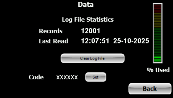
This simple menu is used to show how many records are saved on the Base internal flash memory. The system can hold approximately 125,000 records. The data is stored on the log file and this should be cleared between events. Note that clearing the log file erases all records so do not do this until well after the event has been completed and results have been recorded. The % used bar gives an easy indication of how full the log file is. The Code set button is only used for factory encoding of EchoActive transponders. It is also possible to install new firmware on the EchoActive transponders via this mechanism. Contact info@rfidtiming.com for specific instructions on how to do this.
7.0 Networking Menu
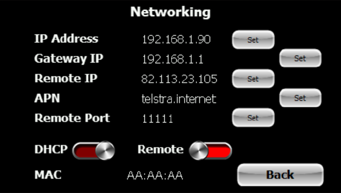
Communication with the Base is either done via ethernet or via the optional 4G modem. In most cases ethernet connection will be used. Ethernet requires a PC with an ethernet jack installed and an ethernet cable plugged into this jack and the rear jack of the Base. Basic networking principles are beyond the scope of this manual but the user should be familiar with how to set the IP address of the computer and the principles behind static and dynamically assigned IP addresses. When an ethernet cable is plugged into an Echo Base (powered on) the firmware will immediately check for a DHCP server and allow that server to assign a dynamic IP address if the DHCP button is turned on. If no DHCP server is found the Base will use the static IP address set under IP Address. When the computer is directly connected to the Base there will be no DHCP server (router) so you will be using a static IP address on both machines. Make sure both IP addresses are on the same subnet (i.e. 192.168.1.XXX). We suggest a subnet mask of 255.255.255.0. It is your responsibility to ensure that there are no IP address conflicts (same IP address for devices) when using static IP address assignment.
7.1 IP Address
This is the static IP address set at power up and will change to a dynamic IP address if DHCP is turned on and there is a DHCP server (i.e. router) on the LAN (Local Area Network). Setting is done by the adjacent button and make sure the IP address entered into the keypad contains the dots between the numbers.
7.2 Gateway IP
If a DHCP server is found this will be populated with the IP address of that server or router. You may also have a router on the LAN that is not in DHCP mode but you can set the gateway IP address to that of the router and data will be sent to the Podium cloud server via this gateway router. If the gateway is connected to the internet then you will be able to reach the Podium cloud server (when Remote is selected) and do firmware updates.
7.3 Remote IP
This is the IP address of the relay server that runs the Podium service. It allows the box to send live timing data to the service where it can be accessed by the Podium scoring software or a 3rd party application that is built to utilise this data. It also allows some settings on the box to be changed remotely. You will need a Podium login to access the data.
7.4 APN
If you are using the 4G modem (optional) the APN is unique to the telco SIM provider. Check with the SIM provider for the correct APN required for data transmission over their 4G network. The modem is an optional extra and must be fitted for it to work.
7.5 Remote Port
This is the port used by the remote cloud server that accepts the transmissions from the box.
7.6 DHCP
Sets the Base to try and obtain a dynamic IP address from a DHCP server on the LAN.
7.7 Remote
Timing data will be sent to the cloud server using either a connected router on the internet or via the optional 4G modem. The router method is tried first before the modem.
7.8 MAC
This is the MAC address of the Base and is unique to the device. It identifies the box when it is connected to Podium PC, Podium Mobile or Podium in the cloud. The MAC is derived from the ethernet chip on the internal RabbitCore processor.
7.9 Bluetooth
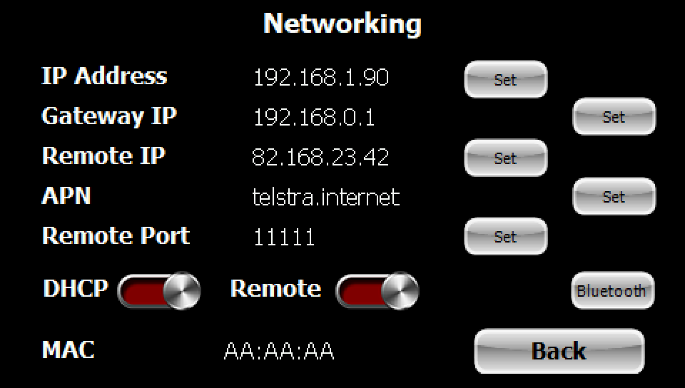
The Bluetooth button on the Networking menu opens the Bluetooth Connections screen. Every Base has Bluetooth Low Energy built in, and it does three separate jobs: it reaches a PC through a USB dongle, it talks directly to an Android phone or tablet running Podium Mobile, and it lets several Bases cover one wide timing point between them.
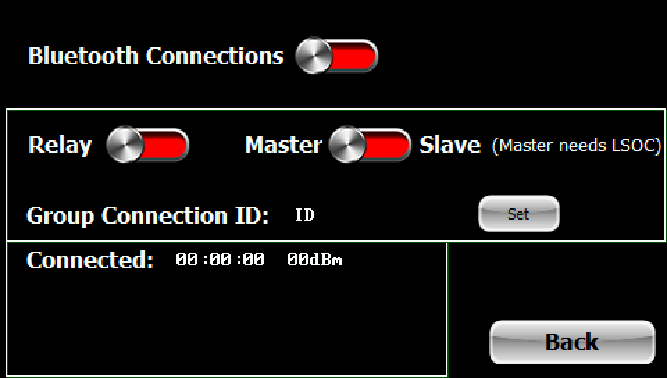
Bluetooth Connections
The master switch for the radio. With it off the Base uses only ethernet and the optional 4G modem. With it on the Base will accept a connection from a dongle or from a phone, and the relay controls below become available.
Relay
Turns on unit-to-unit relaying, where several Bases cover one timing point and report as one. Reads from the outer Bases are passed over Bluetooth to a master, which merges them with its own and sends a single stream out over its ethernet socket. It saves a network switch and a second power supply in the field, and one cable leaves the timing point instead of one per Base.
The relay runs in UHF mode only. In EchoActive mode the radio is occupied with transponders and the relay is shut down.
Master / Slave
Sets this Base's role. One Base on the point is the master and the others are slaves.
A master needs LSOC — a local PC connected to the Base's socket over ethernet. The master has somewhere to send the merged stream only once that connection exists, which is why the screen says so. A slave needs no network connection of its own; its reads leave over the radio.
Group Connection ID
The ID that decides which Bases belong together. Bases sharing an ID form one relay group and a Base with a different ID is ignored.
It is not only a label. Every relayed frame carries an authentication tag derived from the group ID, so a Base outside your group cannot feed reads into your timing point — whether by accident, because another timer is set up nearby, or otherwise. Frames that fail the check are counted and discarded.
Set it with the adjacent Set button, and use the same ID on every Base on the point.
Connected
Shows the linked Base and the signal strength of the link in dBm. A number closer to zero is a stronger link. Use it to confirm a slave has joined before the field arrives, rather than finding out during the race.
8.0 Time
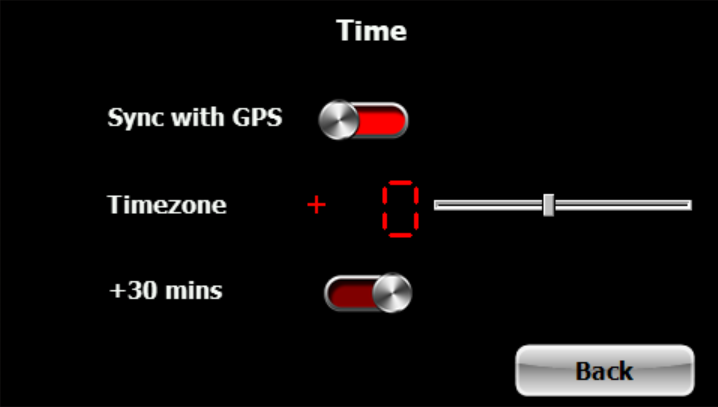
The Sync with GPS option allows the GPS to synchronise the internal clock to the GPS satellite time when the PPS signal is received. This will readjust the internal time keeping clock. If you want to set the time manually using RFIDServer then have this option turned off. Timezone is the time difference in hours from GMT. Use the slider to change to the correct timezone you are living in. The value can be positive or negative depending on which side of the meridian you are. The +30 mins option adds a further 30 minutes to the timezone in the rare occurrence that the local timezone is not a round hour value.
9.0 Other
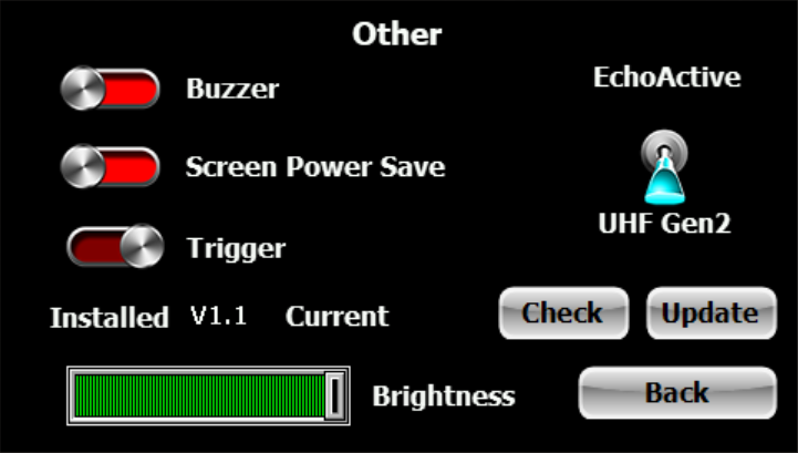
9.1 Reader System
The EchoActive+ is a dual RFID transponder system that can be configured to read either Gen 2 UHF passive tags or EchoActive active transponders. The cyan toggle switch selects which system to use. Note that EchoActive transponders can still be read when in UHF Gen 2 mode as the activation loop is not deactivated. This allows both transponders to be read simultaneously and might be useful in some occasional events.
9.2 Buzzer
All timing systems should have an audible signal of a successful chip or transponder read. The buzzer should be turned on so that the timer has an indication that the system is working correctly.
9.3 Screen Power Save
The sunlight readable touchscreen display in full brightness uses up to 4 W of power and this peripheral uses most of the Base power. The touchscreen is primarily used to set settings on the Base and during timing is only occasionally used to show that a transponder has been read. In most cases the buzzer is enough of a diagnostic tool for the user during an event. It is recommended that if the event is longer than 3 hrs duration (Base fully charged prior) that the Screen Power Save feature is turned on. This will turn the backlight of the screen down to the lowest contrast setting within 15 seconds of no screen touch activity reducing power use by greater than 3 W. This greatly lengthens battery life of the Base during operation. The touchscreen can be re-activated to the previous brightness setting at any moment by just touching it.
9.4 Trigger
This feature is only available at this time in the standard Echo system as the trigger circuit is used for cooling fan control.
9.5 Firmware Update
The current firmware version of the EchoActive Base is shown here as well as on the initial splash screen of the unit on first power up. It is important that the latest firmware is installed. The process to check and install the firmware is as follows:
- Connect the Base via ethernet to a router that has internet access and make sure the Base has a dynamic IP address assigned to it by the router.
- Press the Check button.
- The Base will communicate with our server to see if a new version is available.
- If the Current version is a higher number than the installed version you will be able to press the Update button.
- The Base will download and install the new firmware version. Do not interrupt the ethernet or internet communication during this time.
- The Base will automatically reboot after install. Note that all data will be erased on the log file so do not do this before downloading timing data from the Base for a current event.
Pressing the Update button also puts the internal Bluetooth chip into DFU mode for 30 seconds which allows the chip to have new firmware sent to it over the air using a smartphone app. Firmware updates for the Bluetooth chip are less frequent but may be required from time to time.
9.6 Brightness
As the name suggests this slider changes the brightness of the display. At maximum brightness the display will be readable in sunlight but will also use the most power. When in Gen 2 UHF mode the brightness will be automatically dimmed when the reader is reading and battery power is 50% or less. This is to conserve battery power.
10.0 Base Power Supply
The EchoActive Base V2 operates on an internal 5.0 V and 3.3 V system but external USB power input can vary between 5 and 12 V depending on the specification of the USB-C charger. The power input must come from a certified USB-C plug and not exceed normal voltage ranges as per USB PD (Power Delivery) specifications. A wall plug charger with a minimum power output of 18 W should be used with a full function USB-C cable for charging or external power during operation. Note that the USB-C cable (supplied) must have all the wiring pinouts to complete a USB-C PD fast charge handshake. An approved external USB powerbank can also be used for extra battery supply and most powerbanks are hot-swappable meaning they will not interrupt the Base functions when removed or attached. The internal Li-ion battery is charged by the external USB supply and the internal power management chip controls the supply of current to both battery and system. Note that in UHF mode with the reader in read mode, the unit will be using the most power. If the screen is in full brightness, then external power charging/powerbank will not be able to put a net positive power supply into the system. This means that the unit will eventually run out of battery despite external power being applied. In situations where the Base needs to be running for long periods we suggest using the screen power save option. This will then allow the internal battery to slowly charge whilst maintaining UHF reading function. The Base in Active mode uses half the power that is used in UHF read mode. The internal lithium battery has an NTC circuit for temperature protection during charging. The red charge LED signifies charging and when the green is lit, the unit is fully charged (with USB-C cable attached). If the LED blinks on and off at regular second intervals then there is a charging fault. This may be due to a disconnection between battery and PCB, or the temperature of the battery has exceeded safe limits whilst charging. If this persists then this should be reported to the manufacturer.
11.0 Further Information
(a) The EchoActive Base enclosure is opened and closed using the 2 side latches. To open the latch pull down with both thumbs on the grey section in the middle of the latch. The case can be closed and latched during operation. (b) On very hot days try to keep the case in the shade. The unit does generate heat and direct sunlight on a hot day could put internal temperatures above 70 °C. The internal fan will operate when the reader temperature exceeds 45 °C. (c) The closed case is not waterproof but water resistant. The open case is not water resistant and should be closed if it is raining. (d) The case should be placed on the ground or on a small table and the rear should face the timing point. The top panel has an integrated 2.4 GHz antenna on the top rear of the panel and nothing should be placed near this. This antenna picks up the 2.4 GHz transmissions of the EchoActive transponders. (e) Similar to the 2.4 GHz antenna there should be no objects placed near or over the top of the panel. The GPS antenna on the inside of the top panel requires a clear view to the GPS satellites in the sky. (f) The main PCB inside contains a CR2032 battery cell holder. This battery should be replaced every 2 years as it maintains the internal time of the accurate time keeping chip. (g) Toggle settings on the LCD screen are switched on when the toggle is in the left position and the toggle is lit a brighter red colour.
12.0 Specifications
| Item | Type | Ratings |
|---|---|---|
| Battery — main | x2 Li-Ion pack with NTC | 3.7 V, 75 Wh, 4 hrs run time ¹ |
| — coin cell | CR2032 | 3.0 V, 220 mAh |
| USB | USB-C PD | 12 V, 1.87 A max |
| Charge time | 10 hrs | |
| LCD screen | Resistive touch LCD brightness | Max 880 nits |
| Operating temperature | Base | −20 to +55 °C |
| Transponder | −40 to +85 °C | |
| Transponder (active) | Lifespan | Typically 7 years ² |
| Read gating period | 3 seconds | |
| Weight and dims | 15 g, 39 × 32 × 12 mm | |
| Timekeeping | Temperature compensated crystal | 5 ppm (±0.432 sec per day) |
| Base | Transponder codes/sec | 80 sustained |
| Active loop transmit frequency | 125 kHz | |
| EchoActive receiver | 2.4 GHz BLE | |
| UHF reader | Impinj E710 4 port reader | |
| Modem (optional) | 4G LTE (standard SIM slot) | |
| Flash memory storage | Max 125,000 records | |
| Weight and dims | 1.15 kg, 231 × 173 × 97 mm |
Notes:
- UHF Gen 2 reading mode – full screen brightness and no screen power save. EchoActive mode only > 10 hrs.
- Based on 3000 reads, 100hrs of BT mode and 90% in low power sleep mode, per annum.